

説明
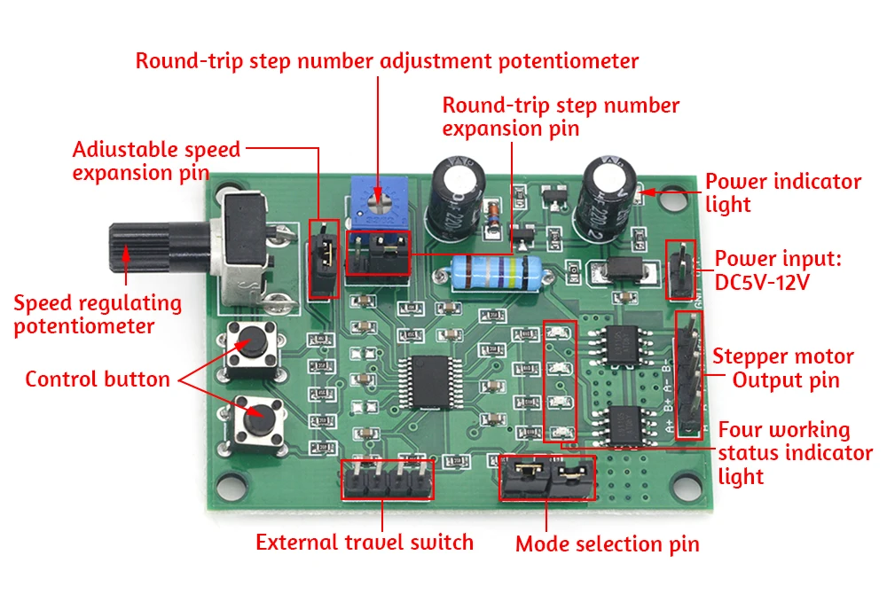
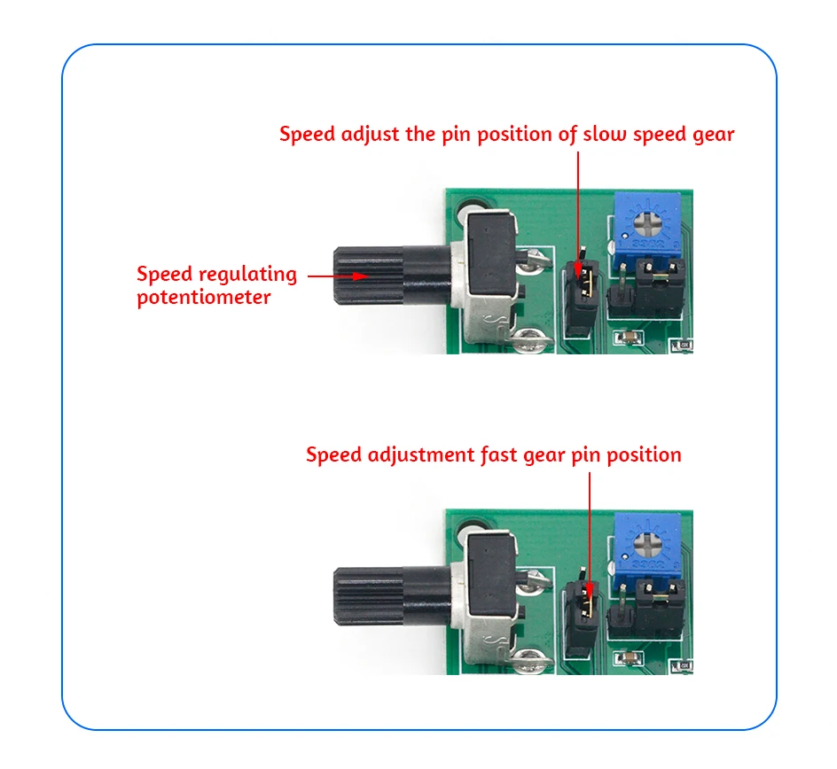
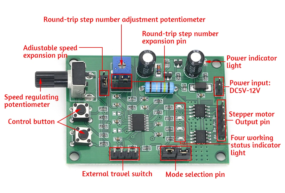
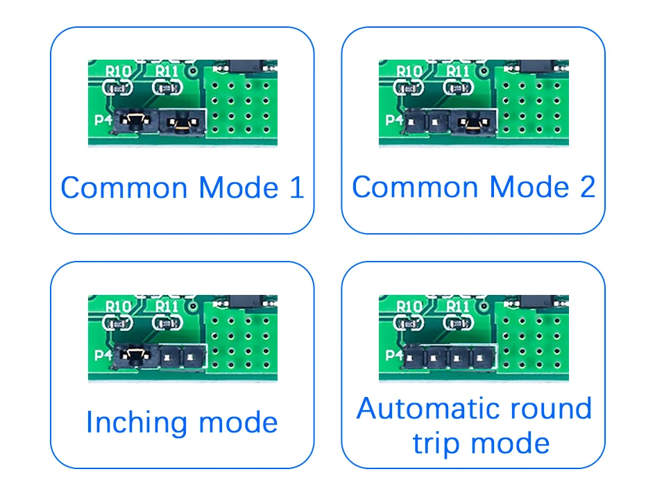
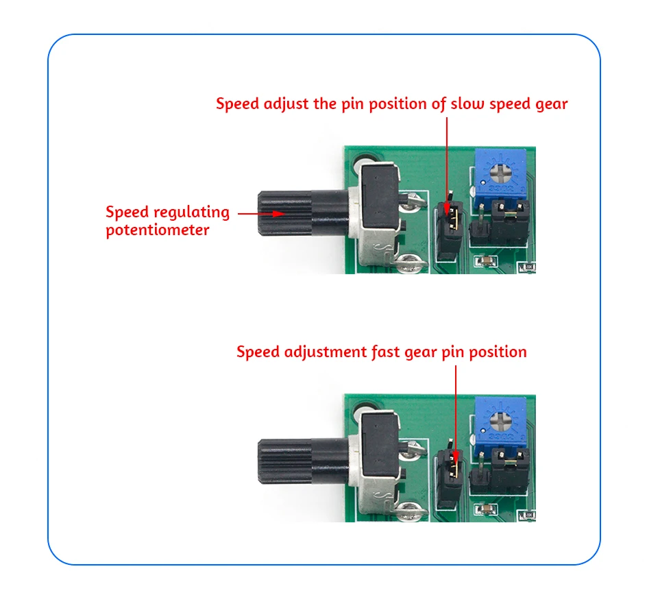
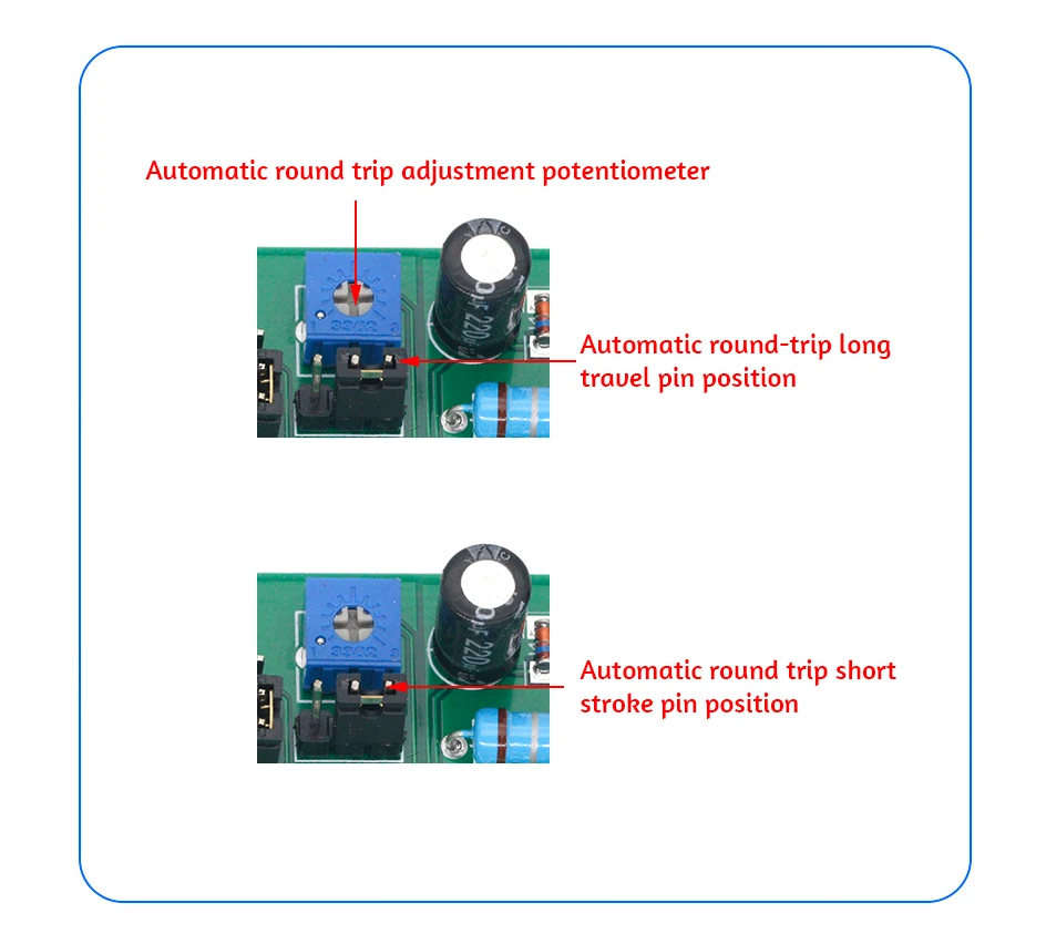
Product Parameters Voltage Range: DC 5V-12V Rated Current: ≤800mA Over-current Protection: Yes Overheat Protection: Yes Power Reverse Connection Protection: Yes Working Mode Drive control board has 4 operating modes to choose: typical mode 1; Normal mode 2; Dot mode; Automatic round-trip mode Normal mode 1: S1 start/stop button, S2 forward/backward button, W2 potentiometer speed management If restrict reversal is required, two limit switches would be related to the P3 pin, and the motor movement shaft is fastened with contacts, in order that the motor will reciprocate within the stroke between the two limit switches Normal mode 2: Click S1 button to begin forwards, S2 backwards, click any button again to stop W2 potentiometer pace legislation If the restrict stop is required, two limit switches would be connected to the P3 pin, in order that the motor will quit transferring when it touches the restrict switch, and the motor will reverse after the opposite button is clicked Jog mode: S1 presses the ahead rotation, releases the stop, S2 presses the opposite rotation, releases the stop, and the W2 potentiometer adjusts the rate If a limit quit is required, the upper restrict switch could be connected to P3 Automatic round-trip mode: S1 starts and stops, S2 is reversed, W2 potentiometer speeds, and W1 potentiometer adjusts the automatic round-trip steps After starting, the motor automatically runs back and forth within the variety of steps adjusted through W1 Functional specs Following determine shows S1 and S2 management buttons with various functions in several modes Please refer to P4 pin function description for particulars Below is the description of W2 and P2 W2 motor pace adjustment potentiometer, counterclockwise adjustment becomes slow, clockwise adjustment turns into instant P2 pace adjustment extension tools pin, W2 adjustment fluctuate is: the slowest three seconds in step with step to the quickest zero seconds in keeping with step (16 steps/second) In rapid mode, the W2 can be adjusted from zero seconds per step (16 steps/S) to zero seconds consistent with step (800 steps/S) Below is the description of W1 and P1 W1 automatic round-trip stroke adjustment potentiometer, counterclockwise adjustment stroke becomes shorter, clockwise adjustment stroke turns into longer P1 computerized round trip adjustment enlargement pin In short stroke gear, W1 can regulate the number of steps from 1 to 200 W1 can adjust the variety of steps from two hundred to 1200 in long stroke tools Figure under is the operate description of P3 pin External stroke change is also used for top and occasional level indicators of various sensors Low point is efficacious The function varies with the mode For details, see P4 Pin function description Following determine displays the pin functions of P5 and P6 P5 stepper motor output pin, in step with whether you select 2-phase 4-wire or 4-phase 5-wire stepper motor, wisely connect the twine in step with the characters at the board P6 power input pin, would be connected to 5V-12V DC power delivery Note: (1) if you wish to replace any operate pins of P1, P2 and P4, you need to disconnect the power delivery at the board and tool at the selected operate again to take effect (2) when the weight latest exceeds 800mA circuit protection, the operating indicator gentle flashing each 2 seconds, then need to lower the working voltage or update the motor can work normally

レビュー
0 people rated this product

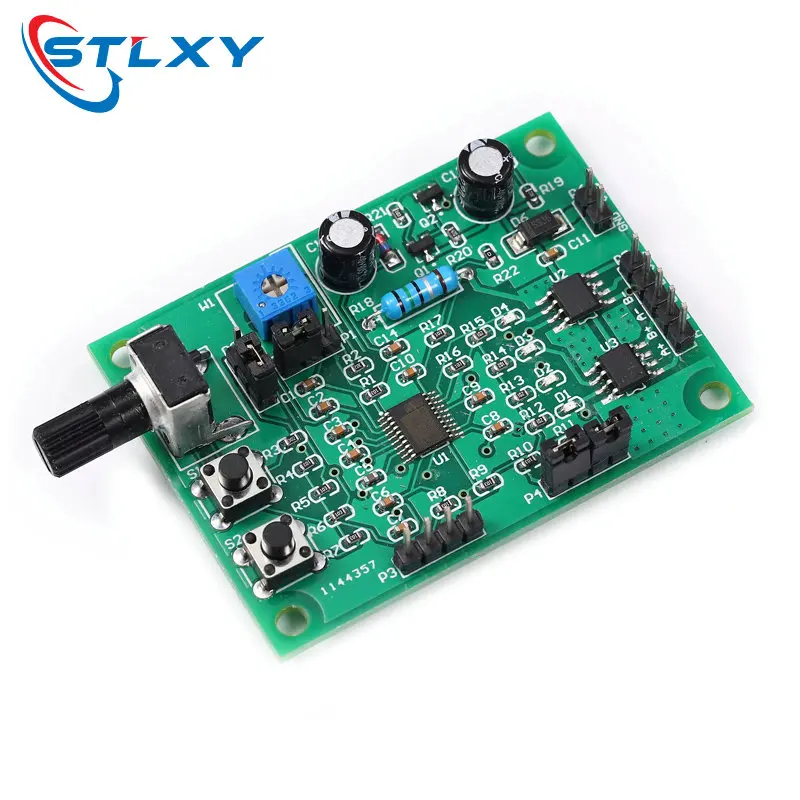
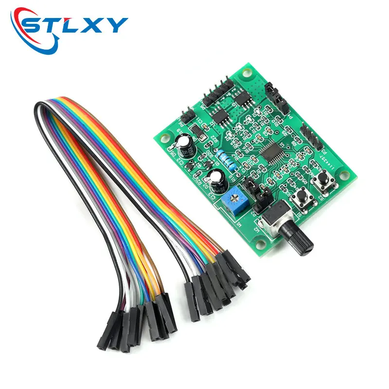
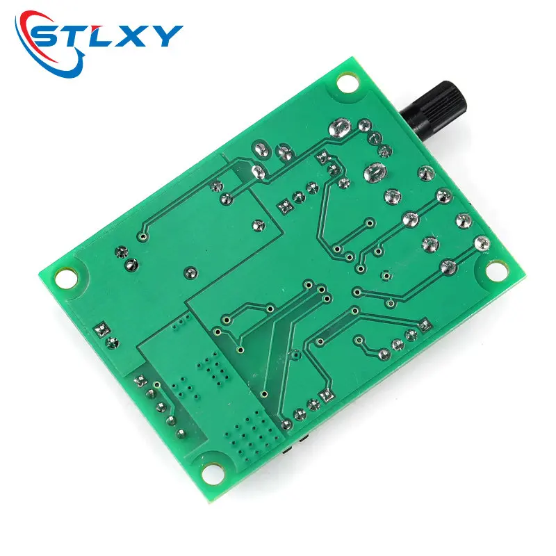
DC 5V-12V 6V Stepper Motor Driver Mini 2-phase 4-wire 4-phase 5-wire Multifunction Step Motor Speed Controller Module Board
配送と返品
 QWQER Express,
 USPS,
USPS, DHL
DHL
Shopping security
- Safe payment options
- Secure privacy
- Secure logistics
- Purchase protection