


Description
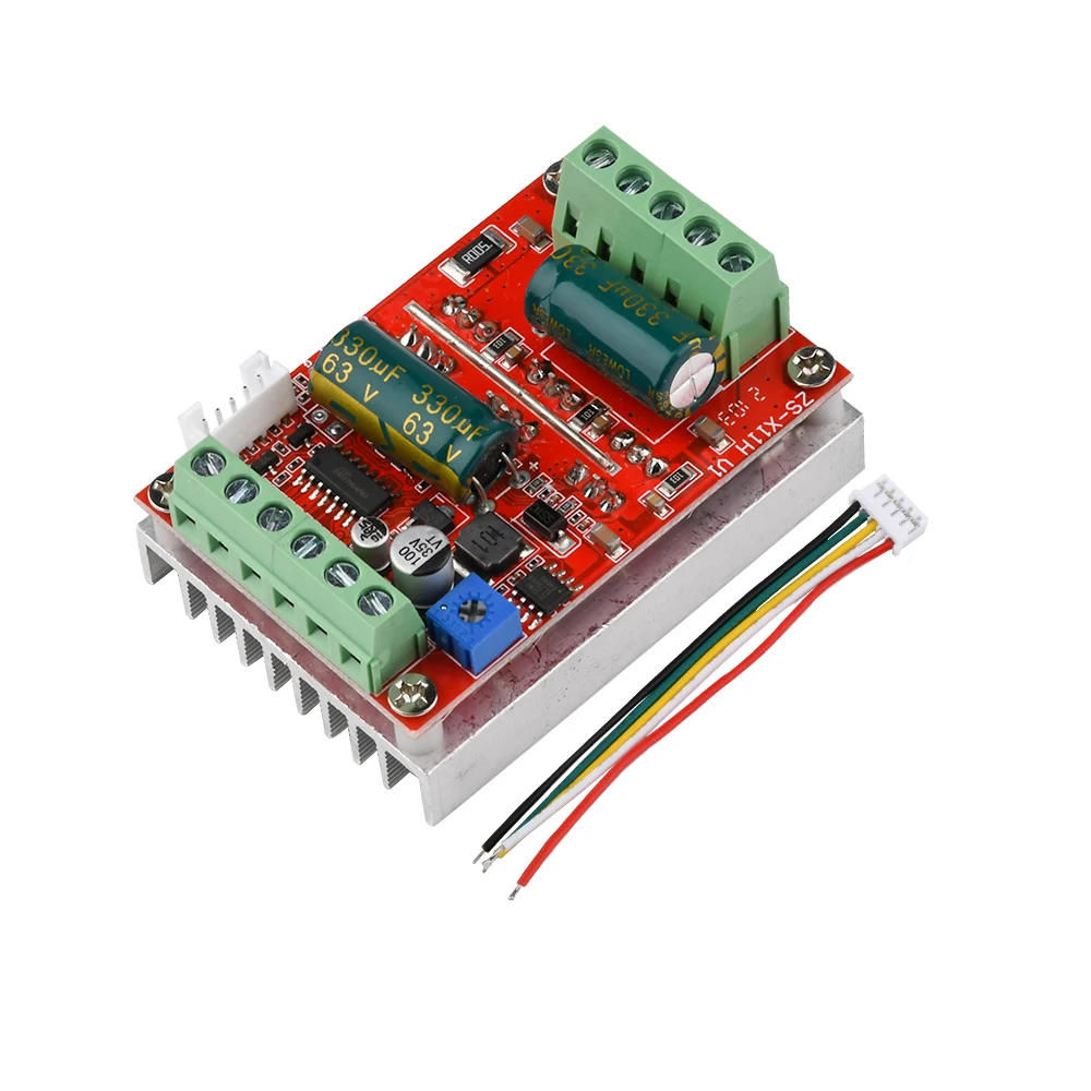
DC6-60V 400W BLDC Three-phase DC Brushless Motor Controller PWM Hall Motor Control Driver Board Motor Driver Module 12V 24V 48V Note: This driver is a DC three-phase brushless control board calls for a motor with Hall to paintings properly This driving force is only relevant to the electrical perspective one hundred twenty degrees DC brushless with Hall motor Newly upgraded BLDC huge voltage 6-60V high power 400W DC three-phase brushless with Hall controller, assist PLC 0-5V analog control support PWM control amplitude 2 External Signal Input Special Instructions: 1 From the motherboard P G 2 ports exterior PWM sign enter (the board comes with a potentiometer to the minimum, while shorting the board quick interface wiring see the diagram above) amplitude 2, frequency 50HZ-20KHZ 2 External analog 0-5V input, from the motherboard 2 terminals sub port input (the board comes with a potentiometer to the minimum, wiring see the above determine dashed line schematic) 3 External potentiometer velocity control, from the motherboard 3 terminals sub port correspondingly linked (potentiometer on the board to the minimum, wiring see the above drawing potentiometer schematic) 4 forward and reverse and forestall by way of a swap to ground (0 potential) low-level valid, can be external MCU to present low-level sign Brake by way of a change to 5V high level valid The entrance row of terminals, are weak signals instantly into the MCU main control, cannot contact and contact with excessive voltage strong current Interface Description: 1 MA MB MC section line output to the motor 2 5V GND leading board with its personal 5V strength delivery (can be exterior power delivery latest does not exceed 50MA) three VCC GND main energy supply (external DC energy supply) 4 SC velocity pulse sign output (only leave out the interface, now not technical support) 5DIR path management forward and reverse control interface (low-level advantageous exterior change to ground) 6STOP give up Stop management interface (low-level valid external swap to ground) 7BRAKE brake control brake management interface (high point legitimate for external change to 5V) eight Speed control pace signal input (on board incorporated potentiometer speed management can be external 0-5V analog PWM twin sign enter pace control) 9 Ha Hb Hc +5V GND Hall sign power supply enter interface, commonly with Hall motors have the corresponding five strains Chip job upgraded performance secure with ahead and reverse stop brake operate Debugging Instructions: please learn and understand before powering at the check machine, it's totally important, very important, very important! After receiving the driver board, first understand whether the interface and your brushless motor interface can correspond on Brushless motor commonly additionally has five Hall line or interface where two is the Hall power delivery line three is the Hall signal line to differentiate out especially the Hall power delivery line (Hall power delivery line generally with purple and black line, there are not, now not clear find a manner to motor brands to) don't make a mistake 3 Hall signal line is usually marked with a b c, the driver board also has ha Hb Hc three ports and other same characters, respectively, akin to join good 2 The motor has three thicker phase line force board also has 3 phase line interface, they're marked with MA MB MC characters and other same characters, respectively, also correspond to connect well, to verify that the foremost power delivery to work properly (Such because the interface are wisely such as the label, the ability can not paintings properly, would not exclude the potential for brands do not standardize the label or different reasons, please stick with the three interface definition is not clean to debug) 3 If the motor phase line and Hall line definition isn't always clear, then the motor would be related to any of the 3 section traces and force phase line interface, whereas the Hall line of the 3 sign traces and pressure the board Hall interface any connection (but the two Hall power supply line must have the option find and attach the right, remember!) Then in the first power on, low voltage small recent debugging (such because the conditions with fixed current power supply voltage to 7-12V current 1-2A), and then by way of arbitrarily swapping the order of the three Hall strains (motor 3 Hall sign line and pressure Hall interface between any two swap, every single change power test), till the ability can be smoothly rotating operation at the appropriate wiring, wiring has six mixtures 1 ha hb hc 2 hc ha hb 3 hb hc ha 4 ha hc hb 5 hb ha hc 6 hc hb ha There are 6 combinations of the above wiring methods, 1 is right, 2 and three motors could also be ready to turn in a single course The different three motors won't rotate 4 fallacious wiring, don't excessive current, high voltage debugging, otherwise there's a menace of damage to the driving force board, 3 Hall sign line swap if the corresponding connected, energy at the motor operating silky tender low-speed birth gentle torque; if the 3 Hall sign line collection does not correspond to the right connection, generally have the ensuing characteristics: 1 1 After strength at the motor can not usually delivery no response or delivery solely shaking when not regular rotation 2 There is a slight jitter start difficulties, and infrequently should be manually to show up three The motor can flip in one direction, the other course cannot flip and a few have a slight tub sound 4 motor start jitter and powerless with a bath sound, the present is large, the ability tube for sure heat critical Humanized design, the interface utilizing the terminal block usual with heat sink incorporated pace potentiometer at the board to the palms of the ability can be utilized to save time and energy Specifications: Product name: 400W brushless Hall DC motor driving force Model: ZS-X11H V1 Operating voltage: 6-60V Maximum current: rated 16A height 20A Maximum power: 400W Overcurrent protection: Yes Product size: size 63MM*width 45MM*height 31MM Weight: about 77g Precautions: 1 The strength delivery circuit on the motherboard with out fuses, Jian Yi has added, the ability supply effective and unfavourable polarity will cause everlasting injury to a couple of the chips on the board (not even for about a seconds at high current) 2 In the traditional operation of the motor output with sampling overcurrent protection, due to module power latest are very extensive please don't paintings within the module is not common man made brief circuit, yet a quick circuit has burned the line burst tube may, the first wiring test machine please use a small recent low voltage test, to be OK, after which during the excessive latest excessive voltage, due to the naked board module on the market word that the wiring cord insulation is strictly prohibited stable voltage touches the board components three Do not connect the obvious and force the module voltage, current, power phase doesn't match or away from the motor, to avoid inexplicable "nonsense" damage


Review
0 people rated this product
DC6-60V 400W BLDC Three-phase DC Brushless Motor Controller PWM Hall Motor Control Driver Board Motor Driver Module 12V 24V 48V
Free shipping & returns
 QWQER Express,
 USPS,
USPS, DHL
DHL
Shopping security
- Safe payment options
- Secure privacy
- Secure logistics
- Purchase protection