


Description
<1>Probe Installations (1) Single- control UP pool( water storage) installation directions shown in figure 1 A( red)— Upper water level management point When water level will get to A point, the probe out of attain water and controller can give up the pump by way of auto B( blue)— Lower water point management level When water point gets off B point the probe out of attain water and controller can start the pump through auto C( black)— Should be placed in bottom of pool because the common line D( green) and E( yellow) are connected with C( black) (2) Single- management DOWN pool ( drain water) set up instructions shown in determine 2 E— Upper water point management point When water level will get to E point, the probe contact water and controller can start the pump by auto D— Lower water point control point As liquid level will get off D point,the probe out of reach water and controller can quit the pump by way of auto C— Should be positioned in backside of pool because the usual line A&B— disconnected (3) Lack of water protection installation instructions shown in figure 3 C&D— Lower water point control features When water level will get off this point, C or D probe out of reach water and controller can quit the pump via auto E&C— short- connected; A&B— disconnected (4) Joint management UP and DOWN pool installation instructions shown in figure four A— Upper water point management level in UP pool When water level will get to A point, the probe contact water and controller can give up the pump by way of auto B— Lower water point management level in UP pool When water point gets off A point, the probe out of attain water and controller can start the pump via auto C— Should be positioned in bottom of UP and DOWN pools as the standard line D— Lower water level control point in DOWN pool When water point gets off D point, the probe out of attain and controller can quit the pump via auto E— Upper water point management level in DOWN pool When water point will get to E point, the probe reach water and controller can delivery the pump by auto <2>Wiring Connection (1) The load capacity shall not exceed the rated skill of this swap at 2500W, Direct control isavailable ( determine 1) (2) The load skill exceeds the rated means of this swap and can be added to the AC contactor( Figure 2 Figure 3 Figure 4) <3>Remove Trouble 1 On strength but no work: a Check the red indicator is on or no longer If not, make the relationship is nice enough; 2 When water point is above or below probes but the pump doesn't beginning or give up through auto, Please verify it like the following a Whether the probe is placed too excessive or low so that water point can reach or out of attain it; b The connection of upper & lower line or probe is disiocation by way of error or brief connected; c To verify the probe whether it is rust or no longer or the relationship is good satisfactory d C- Check the common line whether or not it's placed within the lowermost backside of pool <4> Maintenance 1 To make sure the item work well, p ls test the relationship on input, output and probes whether is nice or now not 2 The user is kindly requested to fasten the probes in the pool so that the probes can live in the precise function and the item can work completely (NOTICE: if the pool is metallic material,C traditional line cannot be positioned in pool, or it is going to be in brief circuit and the object can't work in normal) three Do not install this product into our surroundings of moisture, corrosion and high content material of metal fuel


Review
0 people rated this product
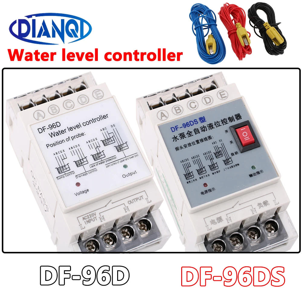
1PC DF-96D DF-96DS Water Level Controller Switch 20A220V Water Tank Liquid Level Detection Sensor Water Pump Controller 2M Wires


Free shipping & returns
 QWQER Express,
 USPS,
USPS, DHL
DHL
Shopping security
- Safe payment options
- Secure privacy
- Secure logistics
- Purchase protection